| Author |  Topic Topic  |
melle
V4 Guru

United Kingdom
3833 Posts | |
AnttiK
V4 Fan

Finland
103 Posts |  Posted - 10 Jul 2020 : 17:52:57 Posted - 10 Jul 2020 : 17:52:57  
| Any progress or new ideas on the 2.9 manifold modification?
I am progressing slowly on the plenum intake aluminium welding, because it is so hard to get the alu weldings airtight with mig. But progressing anyway  |  |
|
melle
V4 Guru
United Kingdom
3833 Posts | Posted - 10 Jul 2020 : 18:57:43
| Yes, a little progress, but not much. Will update when I have time, don't hold your breath!
www.saabv4.com | |
|
melle
V4 Guru
United Kingdom
3833 Posts | Posted - 19 Jul 2020 : 21:36:40
| I've not had much time lately, but still a tiny bit of progress.
I wanted to estimate the volume of the manifolds for both the EFI and the K-Jetronic MFI engine, so I did a little measuring. Nothing scientific, just taped up/ plugged all the orifices apart from the top ones and filled the holes with tap water. My method was filling a bottle, weighing it, filling the volume I wanted to measure, weighing the bottle again and calculating the difference. Being more accurate, like you would do for combustion chambers, doesn't make much sense at this stage.


EFI V4
The total volume of the plenum and the manifold is approximately 3l, of which the part I'll be losing makes up about a third, so I should end up with roughly 2l intake volume, which I think is ample for a 1.7l engine. The runners are about 18cm long, looks like Ford did a nice job designing this intake (it also looks so much better than the ugly square 2.8 K-Jet plenum!).
I'm convinced the V6 TB butterflies are way too big though (2x Ø45mm opening simultaneously), so I designed an adaptor to fit a progressive TB from a MK2 Golf/ Audi 80/ Porsche 924/ etc., of which I have a few, and an idle air passage, which is normally incorporated in the V6 TB.

I still haven't had time to look into the Speeduino ECU again. I think I may have blown up some of the LEDs by testing circuits with a 5V power source; I didn't realise they are 2V. I've bought 50 new ones, so I hope I have enough to fix the issue!
K-Jetronic V4
The (lack of) volume of the V4 inlet is a little more worrying as I suggested earlier. I measured the manifold itself at a meagre 285cc, and with my spacer added the total will be approx. 370cc after the TB, which is less than ideal I suppose. According to most of the engine tuning books I've consulted, you want an inlet volume of at least 80% of the combined cylinder volume. The standard inlet + my adapter yield only 27%. I wondered if it would help if I add volume before the TB butterflies, i.e. a long tract between the fuel metering head and the TB?
I pulled an injector from my Saab 900 to get some dimensions from. I noticed the seal had turned into toffee; according to my notes I installed it in 2016, so the quality is rather disappointing as usual...

To my taste, 900 injectors are on the long side for the V4 manifold, so I decided to splash out on four brand new Mercedes injectors, which are a little shorter, and surprisingly cheap (less than £75 for a set). Different (no) brand seals this time, hope these last a little longer.

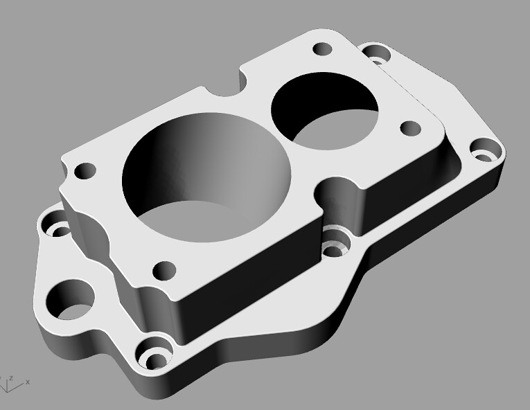
I knocked up the top end of an engine in CAD a while ago, and decided to build a physical mock-up too when I was able to get some ply and threaded rod from B&Q again. My mate will 3D-print some throttle body adaptors when he gets to it, and then I can mock up the injector bosses.

Annoyingly, all the K-Jet parts I've amassed over the years are in my workshop in NL, so I bought yet another Audi TB so I can keep the ball rolling. It isn't the exact one I'll be using, but it was the cheapest one I could find that is about right.

If I could easily access my workshop, I wouldn't use all the workarounds, and things would likely progress a bit quicker. Anyway, I'm not racing anyone and I'm glad I can at least keep messing with these projects. That's all for now, more when it happens.
www.saabv4.com |
Edited by - melle on 19 Jul 2020 21:41:12 | |
|
RhysN
V4 Fanatic

United Kingdom
411 Posts | Posted - 20 Jul 2020 : 07:26:53
| | Stunning work Melle, your attention to detail amazes me. | |
|
melle
V4 Guru
United Kingdom
3833 Posts | Posted - 12 Aug 2020 : 16:33:21
| Small steps again, but progress is progress. I had a stroke of luck and found both the throttle bodies I want to use for the EFI and K-Jet conversions on eBay a few weeks ago. I already had one of both, but they're in NL. Until recently I'd been making do with a TB from a Golf for my mock-ups, which was similar enough to both, but slightly different in critical places. My friend 3D-printed throttle body adapter prototypes for both conversions for me.
EFI
For this conversion I'm using an Audi 80 throttle body. I wasn't entirely happy with the thin adapter I'd designed earlier, as the flow from the butterflies to the plenum was very abrupt. There also was an interference issue with the ECU temperature sensor that I'd forgotten about. I could move this sensor to a boss at the other side of the thermostat housing, but a 30mm thicker adapter seems to work out better on all fronts. New CAD drawing nearly ready for 3D-printing.
Test fit:

Interference with coolant temperature sensor and mock-up of new adapter dimensions:

Boss that could be drilled and tapped for the sensor:

New adapter design:
I have a generic K&N cone filter that I picked up from a car boot sale a long time ago that I think will work nicely with the Audi TB. I'm looking for one of these rubber elbows from a MK2 Golf/ Jetta 16V GTI for an air filter adapter, please let me know if you have a spare.

I've decided I want to retain the full length of the plenum, and only shorten the manifold, just because it looks good (see above photo). I'll still need to remove the internal partition, and block the rearmost runners in a visually acceptable way. I think I've found a way of making it all work, more on that later. I have a pair of standard Sierra V6 pressed steel rocker covers that I'm going to shorten, should look the part when done.
I've also come up with a solution for the slight issue that the mounting holes in the V6 inlet manifold are spaced differently from the V4 hole pattern. I'll think what I'll do is ream the holes in the V6 manifold to 8.98mm and plug them with 9mm round bar stock, maybe with a drop of loctite added for good measure. I can then drill new holes using a V4 manifold as a template, and where the bolts happen to interfere with the intake runners I'll drill and ream them to just under 1/2", fit a thick wall aluminium tube and ream the ID to 8.5mm when it's in place. I can weld the tube in place if needed. I think interference will be minimal, and there is no interference with coolant channels.
I'm not exactly sure what radiator I'll be using yet, probably Saab 9000 or Peugeot 307 (I have both) if I can get one of those to fit between the headlights, but the standard Ford V6 thermostat housing outlet most likely faces the wrong way for my application. Also, the one I have is badly corroded internally and new ones are almost as expensive as having a custom one made. I've drawn up one with a separate pipe that rotates in the hole. When 3D-printed it can be test fitted to an engine and clocked (marks on plate and pipe) in situ. This is much easier than guestimating or measuring in thin air. The final product will be one piece and cast in aluminium or billet machined, not sure yet.

K-Jetronic
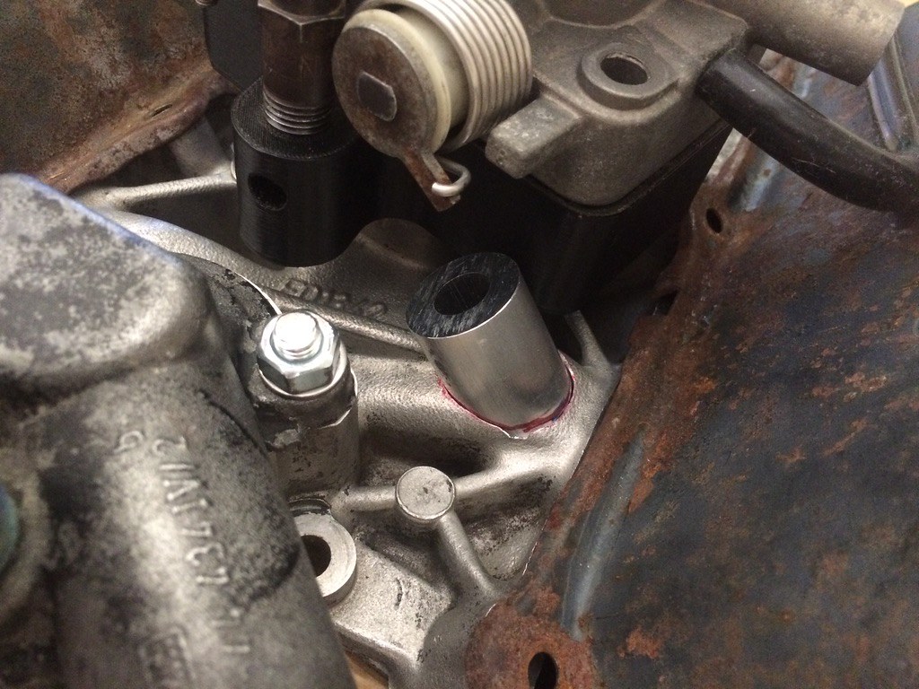
Dirtbiker and Dynorog kindly donated two manifolds to the cause, so I could do some experimenting with cutting seats for injector bosses without the correct tools (i.e. a vertical mill, or at least a decent pillar drill). Even though I'm clearly not set up for machining cast aluminium manifolds in the kitchen, I'm reasonably happy with the results so far. The aluminium itself is a pig to machine, it's very gummy as you'd expect with a cast part, but my trusty Wolf Sapphire 70 drill and a cheap Chinese tungsten carbide 25mm hole saw (https://www.ebay.co.uk/itm/353133150159) worked fine. Not sure how long the saw will hold up as the material is really tough on the carbide teeth. I'll order some spares, they're cheap enough. I don't want to use WD40 or cutting fluid as I'm trying to minimise contamination of the material for the welding.
Centre drill first, then cut a hole/ seat:

Injector boss seat cut and reamed to size for the 1" tube (1" = 25.4mm):
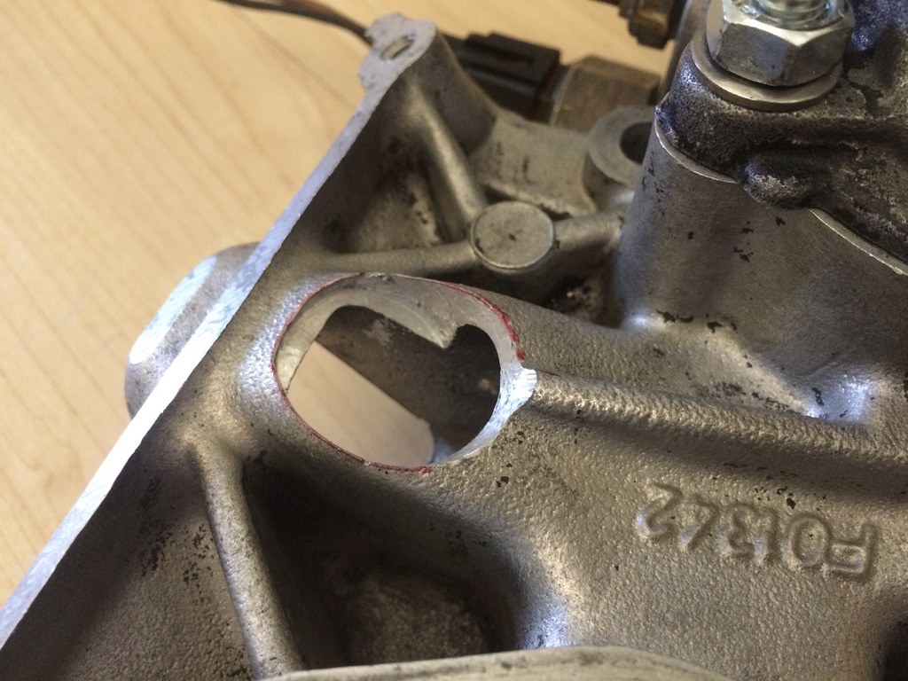
Injector boss in place:
Next time I'll knock up an angled jig from some 18mm ply and cut some more practice seats, two of the bosses need to sit at an angle because they interfere with the TB.
The bosses are 1/2" ID. The idea is to TIG weld them in place, drill and ream them to 14mm for the injectors and port match the manifold to the heads and remove all excess material from the bosses inside the ports. The injectors will just push in, I don't think they'll need retainers.
Inside will need porting:

The throttle body adapter I designed fits fine, but I've made some minor improvements so hopefully the next 3D print will be the final prototype before milling.
Adapter with Porsche 924 TB in place:

I'll not be using this type of rocker covers, so there will no crankcase ventilation system pipe next to the fifth injector on the final product.
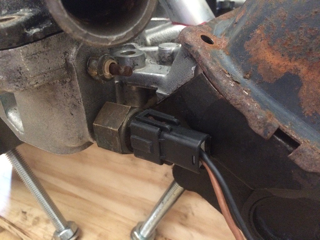
The thermo time switch plug interferes with the n/s head in its current location, will swap it with the temperature sender on the next prototype and see if that works better. If all else fails I can fit it to the front of the manifold, but that'll look daft in my opinion.
If anyone happens to have Porsche 924/944 inlet ducting kicking about, please give me a shout. The boot that fits on the TB is the most important, but I'll gladly take a whole assembly.

That's all for now, updates when more progress is being made.
www.saabv4.com |
Edited by - melle on 12 Aug 2020 16:45:21 | |
|
AnttiK
V4 Fan
Finland
103 Posts | Posted - 12 Aug 2020 : 17:56:50
| Good progress Melle I have also noticed when making modifications there are always this kind of things like the temperature sensor location and I personally think it is fun to have technical challenges.
During my summer holiday I managed to make first functional prototype of the plenum manifold and it is installed to the car. I think I make some modifications to the plenum shape and then it will be painted. Also I am going to do some stainless steel hoses and box for the air filter to get fresh cold air to it and hide it, because I think this kind of 'tuning' filter is quite ugly. Also temporarily lengthened V4 throttle axle must be replaced by solid 6mm axle etc.

I have not noticed much difference in car behaviour. Probably more torque in low revs and more power in the highest revs, but I think those are quite small differences, when compared to standard manifold. But I think it is as good as the std manifold or better | |
|
melle
V4 Guru
United Kingdom
3833 Posts | Posted - 12 Aug 2020 : 19:11:55
| That looks great! Feel free to post a few more photos from different angles. I'm totally with you on the technical challenges! 3D-printing is a great tool to prototype potential solutions.
I agree, cone filters are ugly. The one I'm planning to use for the EFI engine looks similar, but is from K&N, so reddish/ brownish rather than bright blue fortunately. I think boxing it in and shielding it from the exhaust downpipe is a good idea, it may also muffle the intake noise a bit? I hate "sports" filters, but at the moment there's nothing else I can think of that works with the V6 plenum.
www.saabv4.com | |
|
AnttiK
V4 Fan
Finland
103 Posts | Posted - 12 Aug 2020 : 19:57:04
| Here is a picture from the other side. I had to modify the plenum to make the fuel rail fit under it. I did not want to install injectors further away from intake valve, because according to literature low rev performance is better when injector closer to the valve and I think it looks cleaner this way.

Also here is a picture of lower part of the manifold. As can be seen I am using silicon hose and clamps to connect upper and lower parts of the manifold.

Yes, muffling the intake noise is also important purpose for the air filter boxing. There is a good space for the air filter box below/behind the left headlight. At least in my Saab, where I am using ford focus radiator and water reservoir located in different place from original. | |
|
AnttiK
V4 Fan
Finland
103 Posts | Posted - 13 Aug 2020 : 06:07:18
| quote:
Originally posted by melle
I'm not exactly sure what radiator I'll be using yet, probably Saab 9000 or Peugeot 307 (I have both) if I can get one of those to fit between the headlights, but the standard Ford V6 thermostat housing outlet most likely faces the wrong way for my application. Also, the one I have is badly corroded internally and new ones are almost as expensive as having a custom one made. I've drawn up one with a separate pipe that rotates in the hole. When 3D-printed it can be test fitted to an engine and clocked (marks on plate and pipe) in situ. This is much easier than guestimating or measuring in thin air. The final product will be one piece and cast in aluminium or billet machined, not sure yet.
It was quite hard to find radiator, which is not too wide. Focus I 1.6 radiator without air conditioning was quite tight fit between the headlights. I am going to modify the headlight metal frames to get the radiator top few centimeters forward. Focus radiator is quite thin, it is new and it was quite cheap (30+shipping costs). | |
|
melle
V4 Guru
United Kingdom
3833 Posts | Posted - 13 Aug 2020 : 11:17:23
| I like your solution with the hoses to connect the plenum and the manifold, never thought of that.
Not sure if your throttle body is modern enough to accept a throttle position sensor with a motor, or if you can find a modern variant that already has one, for fly-by-wire control? That way you don't need the throttle shaft at all, but you will of course have to modify the pedal.
Are your injectors just a push fit in the seats, or do you use anything to retain them? What's in the distributor hole? Modified cam sensor from another car?
Someone on here fitted a 9000 rad, can't remember if his car has US head lights. The mounts will need modification, but that's not an issue for me. I also have a Ford Fusion 1.4 petrol radiator + fan that should work. I'll use a pulling fan in front of the radiator anyway and some shrouding to force the air through the rad.
www.saabv4.com | |
|
AnttiK
V4 Fan
Finland
103 Posts | Posted - 13 Aug 2020 : 11:56:01
| quote:
Originally posted by melle
I like your solution with the hoses to connect the plenum and the manifold, never thought of that.
In the beginning I had plans to make the flanges to connect upper and lower part of the manifold. Actually the idea came from my friends TVR cerbera, which has silicone hoses as intake runners if I remember correctly. There is much more space for fuel rails and other equipment now. And also upper part is quite easy to detach.
quote:
Originally posted by melle
Not sure if your throttle body is modern enough to accept a throttle position sensor with a motor, or if you can find a modern variant that already has one, for fly-by-wire control? That way you don't need the throttle shaft at all, but you will of course have to modify the pedal.
Peugeot 306 1.6 50mm throttle body is from year 1996 I think and it is not easy to modify it to fly-by-wire type. But the throttle body itself is quite simple and slim. I had to modify it a little bit to fit it under the bonnet. Longer throttle shaft works very well and I think it is reliable so I am probably going use it in that way.
quote:
Originally posted by melle
Are your injectors just a push fit in the seats, or do you use anything to retain them? What's in the distributor hole? Modified cam sensor from another car?
Just a push fit. Fuel rails are fastened to old 1 barrel carburettor fastening bolts with a steel structure, so the injectors stay in place very well. Cam sensor is ford VR sensor and I modified to the V4 distributor with DIY steel structure (draft version  ) )
| |
|
melle
V4 Guru
United Kingdom
3833 Posts | Posted - 13 Aug 2020 : 12:39:16
| Ah yes, forgot about the fuel rails. The K-Jet system doesn't have them, there are individual lines from the fuel distributor to the injectors.
I wouldn't be surprised if your TB has a standard bolt pattern and versions with a spindle motor are readily available. They will of course be a bit bulkier. Just had a quick look on eBay, looks like (some) 307 TBs are FBW, not sure if they have the same bolt layout as yours?
Be interesting to see more about your cam sensor design. I don't need one as I'll be going batch injection, but interesting for future reference for sure (and because I'm always eager to learn about clever engineering solutions!).
www.saabv4.com | |
|
AnttiK
V4 Fan
Finland
103 Posts | Posted - 13 Aug 2020 : 19:14:49
| I tried to take a picture from cam sensor bracket structure, but it is below fuel rail, intake manifold and the hoses so I did get a proper picture of the bracket. I have cut the aluminium "cup" away from the V4 distributor, cut the rotating part smaller that it will fit inside the 38mm steel pipe. And this steel pipe is connected with self made clamp to the distributor stem. And I have made also small bracket for fasten the VR sensor to tube. cam sensor needs only one tooth to indicate which one of the engine cycle is ongoing, so the structure is quite simple.
Sequential injection is quite easy to add afterwards, if you have separate control outputs for individual injectors and i.e 36-1 trigger wheel sensor is connected directly to the ECU. In example I had to get rid of EDIS-4 control unit, because it outputs only one pulse to ECU in engine cycle. And also ECU must support sequential injection.
Even if some other throttle body had different pattern, I can easily drill different pattern to the flange or replace the flange to another. |
Edited by - AnttiK on 13 Aug 2020 19:15:32 | |
|
v4admin
Forum Admin

United Kingdom
522 Posts | Posted - 13 Aug 2020 : 20:22:00
| | amazing work going on here! | |
|
| Topic | |
